Some Tough ECE Questions
Posted by Subash | 10:06 AM
[1] Comments


Some of the most toughest ECE Questions from my collection. Presented here in the form of images by taking snapshot from some pdf files. They are from assignment set for a particular course of an american university.
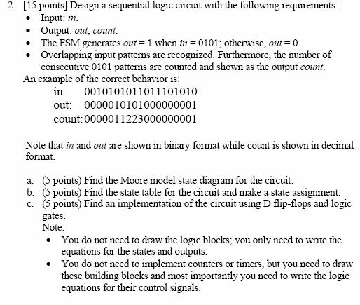
- Using adders, shifters, multiplexers, registers (flip-flops), and anything else you need, sketch the data path for an 4-bit multiplier that takes 4 cycles to generate an 8-bit unsigned product from two 4-bit unsigned inputs.
- A FSM for an anti-lock brake system accepts two inputs – wheel and time, and generates a single output – unlock. The wheel input pulses high for one clock cycle each time the wheel rotates a small amount. The time input pulses high for one clock cycle every 10ms. If the machine detects two time pulses since the last wheel pulse, unlock is asserted for one clock cycle. After unlock goes high, the machine waits for two time pulses before resuming normal operation. Thus, there are a minimum of four time pulses between unlock pulses. Draw a state diagram (bubble diagram) for this state machine.
- In many communication and networking systems such as 100Mbit Ethernet, the signal transmitted on the communication line uses a non-return-tozero inverted (NRZI) format. You are to design the circuit that converts any message sequence of 0s and 1s to a sequence of NRZI format. The NRZI encoding rules are as follows:
a. If the message bit is a 0, then the NRZI format message contains an immediate change from 1 to 0 or change from 0 to 1, depending on the current NRZI value.
b. If the message bit is a 1, then the NRZI format message remains fixed at 0 or 1, depending on the current NRZI value. The NRZI encoding rules can be illustrated by the following example, which assumes that the initial value of the NRZI message is 0:
Message: 10001110011010
NRZI Message: 00101111011100
a. (5 points) Find the Moore model state diagram for the circuit.
b. (5 points) Find the state table for the circuit and make a state assignment.
c. (5 points) Find an implementation of the circuit using D flip-flops and logic
gates.
10:07 PM
Hi Subash,
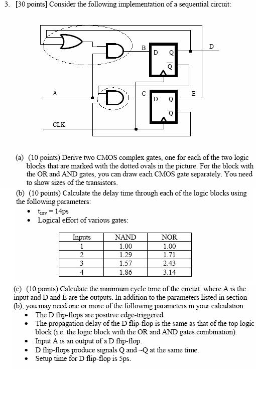
Can you provide the answer to the 3rd question where we have to design the CMOS complex gates. Couldn't get the transistor sizing part.